Building the Vulcan.
(Three years and still not finished)
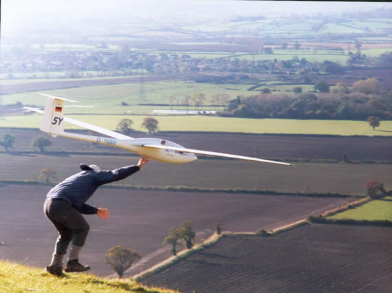
Dave Cox describes the progress so far on his current building project.Most modellers I know would expect to see me arrive at the slope with either a scale model or the F3J Stork. Given the right conditions my preference is to fly scale and go for a cross-country walk along the downs.
My scale gliders have all been bought second hand and the only building involved has been to refurbish or make repairs. A recent example of this was a quarter scale ASW28 that I bought second hand last year. On first inspection it looked to be in good condition with only minor damage and I was surprised the model was for sale at such a good price. There were however some obvious problems with the way the controls had been installed .The elevator linkage was horrible sloppy and caused huge amount of slack. The rudder hinge was not in line with the horns of the close loop and so would not centre. The combination of these problems would have made the glider almost unflyable, hence the reason for the sale. The problems were easily resolved by installing a servo in the fin with a direct linkage to the elevator and the rudder was repositioned. Following these alterations the model was successfully launched and is a joy to fly.
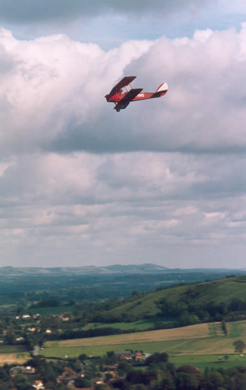
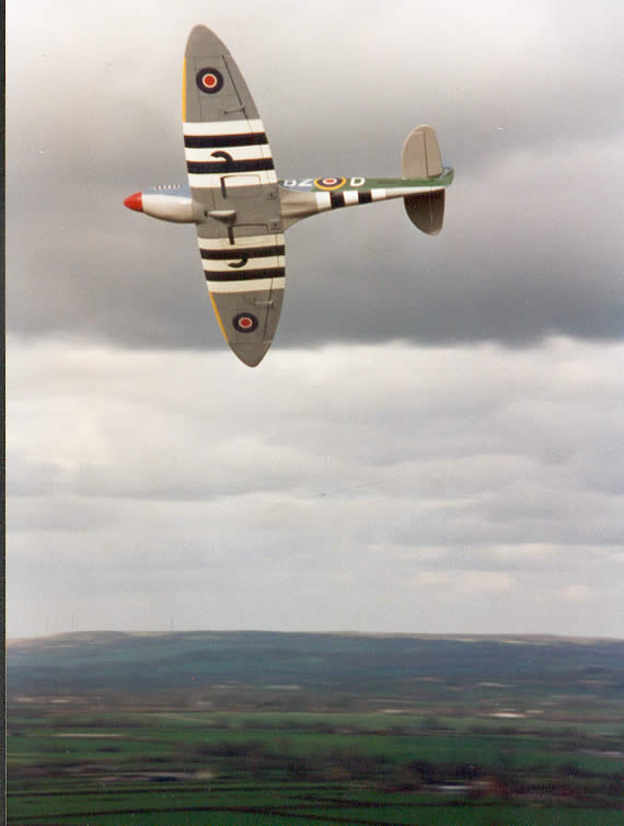
Every few years I undertake a major new building project. The types of models I build are intended to be very different from the scale and high performance machines. Example include a quarter scale Tigermoth built from the Flair kit, a large Mk 9 Spitfire from Flying Legends, a model bird and an old damaged scale model converted to hold a video camera on a revolving turntable.
The Tigermoth and Spitfire were built from kits and only needed minor alterations to be converted to slope soaring. The Tigermoth was built from Liteply and balsa. It will happily stay up in a 12-mph wind and looks great flying at a scale speed .
The big Spitfire on the other hand has a moulded fibreglass body and foam wing. It is therefore much heavier and need 25 mph on a good slope to fly. In the air it looks superb and has been mistaken several times for the real thing .
The video-carrying plane was a damaged quarter scale Grob. I built the turntable into the cotpit using pluming pipes. The revolving mechanism was simply the screw thread where two pipes joined together. A Hitech quarter scale winch servo intended for yatching drives the turntable allowing it to revolve 360 degrees. This allows me to pan the camera in the air.
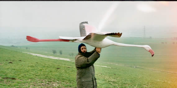
In contrast the bird was completely scratch built, using mainly white foam and ply. The design was based on one picture in a bird book and scaled up to 150 %. The bird chosen was the Greater Flamingo. When completed it looked superb, but was difficult to fly due to poor elevator stability. I had used the bird’s tail as the elevator but this was too near to the c of g .The damage from a poor landing has been largely repaired, but the design needs to be changed to improve stability. My current thinking is to build a tailplane from clear plastic and mount this near the feet, giving a longer moment arm. I thought it would make a great April fools joke to photograph a Greater Flamingo soaring over Beachy Head. More proof of global warming!
So now I’m building the Vulcan. To be accurate, it is an Avro Vulcan B.MK.2.Why choose a Vulcan? Well, I first saw the Vulcan fly at the Farnborough air display in the 1970`s. The four Rolls Royce engines shook the ground as this 50 ton bomber put on a display of aerobatics most fighters of the day could not match.
The early designs for a bomber produced by A.V. Roe were similar to the Northrop flying wing. But this design had problems with stability making it less accurate on bombing trails.So the Vulcan was amended to have a longer nose and the wingtip fins were replaced by a central fin to give the characteristic delta shape.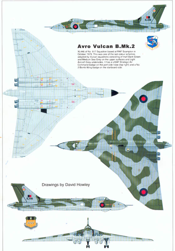
The prototype was first flown in 1952. After several years of development the design was improved until the B.MK. 2 became the final version. The Vulcan was designed primarily to fly high and fast carrying nuclear free fall bombs. Later these were replaced with Blue Steel missiles that could be launched from a safer distance. The Vulcan fortunately never fulfilled this role and only saw service in the Falklands during 1982. The Vulcan squadrons were finally disbanded in 1984, leaving one plane flying at public displays. Today it is being restored to flying condition and could be in the air within the next to few years.
As a potential slope soarer the Vulcan has a low drag profile and a large wing area. A design not suitable for F3F or F3J but given a 20-mph wind on a good hill it should be an impressive sight.Having decided to build the Vulcan I looked around for detailed information and purchased a booklet from the series called Warpaints. This gives the background history and has lots of detail pictures specifically to help modellers. It does not however give construction advice and I was keen to know important details such as a suitable wing section and the C of G.
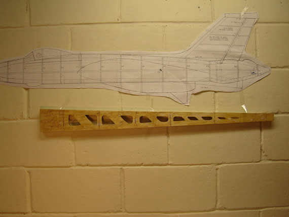
I saw in one of the modelling magazines an advert for construction plans and one of the planes included was the Vulcan. The plans showed construction details for a 5ft span powered model. It cost about £10, which seemed worthwhile for the help it would provide.
The two large sheets that arrived showed a model of built up construction. This included plans and sections plus the outline of individual components such as ribs and formers. It also showed information that I didn’t need, so my first job was to paint over and remove the engine, fuel tanks, servos etc. I then compared the plans to the Warpaints book and made many minor changes to improve the profile and scale details. I intended to increase the size from 5 to 10 ft span which would make it much heavier and so the structure would need to be strengthened. I anticipated an all up weight of 25 lbs and so changed the structure including stronger spars. With all these changes made I finally had half size plans for the model, as I wanted to build it.
A project of this size needs a lot of materials. Ideally I would use Liteply, balsa and 64th ply. But these are very expensive and would cost hundreds to buy. The wing area for example is 25 sq ft so covering top and bottom in 64th ply needs 50 sq ft ! My approach is to use cheaper materials available from the DIY stores plus whatever I can find to adapt.
I checked the DIY stores and found a wide variety of thin ply sheeting. Most were too heavy, but some sheets of the same thickness were much lighter. I bought two different grades. The heavier for the high strength areas such as the spars and longerons and a lighter weight for the wing ribs and body formers.
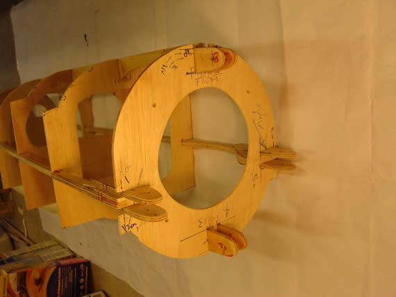
My revised plans were again copied and the individual components cut out. These individual pieces were still at half the final size and so they were each copied again and this time printed out at twice their size, which was correct for the actual size of the model. So now I had all the main components drawn up on paper templates.To produce the ply pieces, the paper template was stuck onto the ply. When a matched pair was needed such as left and right wing ribs, two pieces of ply were tacked together. Then using a bandsaw the matching ply components were cut out.
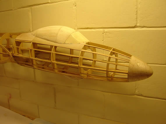
Given the size of the Vulcan wing, the rib nearest to the body is 5ft long and 8 inches deep. Holes were then cut in the ribs for the spars to go through and further holes cut to reduce weight and make the finished item.

The construction of the spars was based on the method used on the Tiger Moth. That is a box section made from two lengths of ply held apart by two balsa spacers top and bottom. The heavy ply used was lightened by cutting numerous holes.
Some time was spent estimating just how strong to make them. My calculation was that a 25lb Vulcan doing a loop could pull 3 Gs, giving 75lbs of weight to support. In all 4 spars are used in each wing. The first being short and stubby, the second and third being the main load bearers and the fourth spar doubling as the trailing edge onto which the elevators and ailerons are hinged.
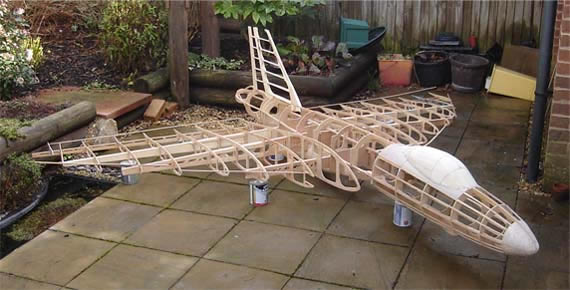
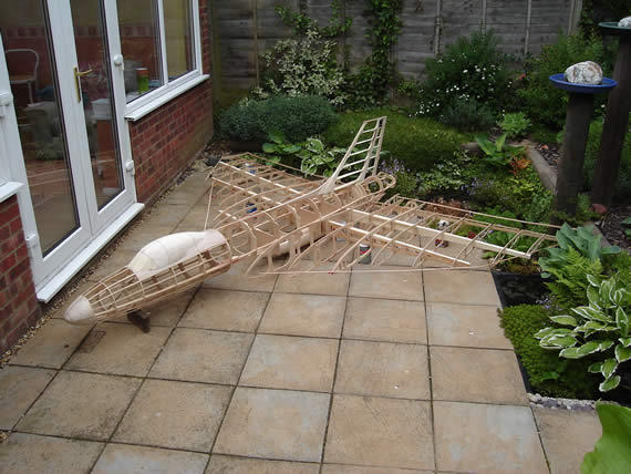
To this point the project had taken two years and no two pieces had been glued together. Large piles of finished components were ready and so work started on the construction.
During 2005/6 the body was assembled and details added, such as the cockpit and the Blue Steel missile .
Work also continued on the wing’s trailing edge and elevon hinges, but no assemble yet made to the wings.
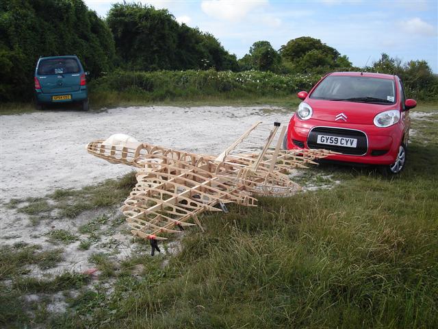
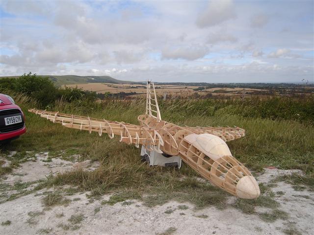
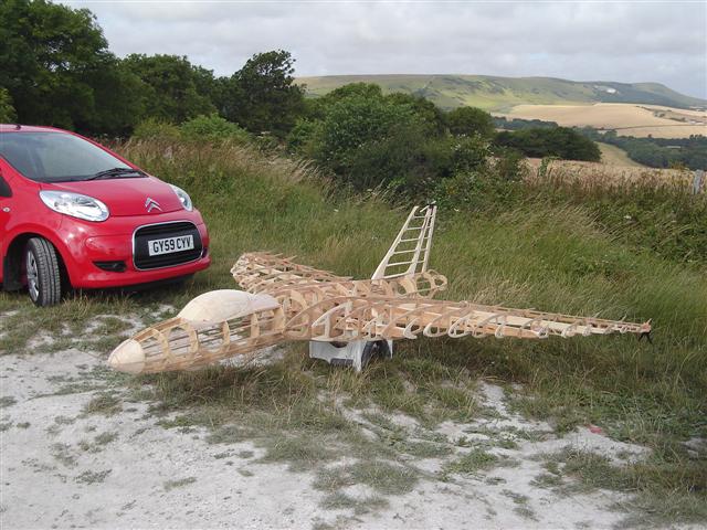
As assemble continues into 2007, the fin and rudder have been added to the body.
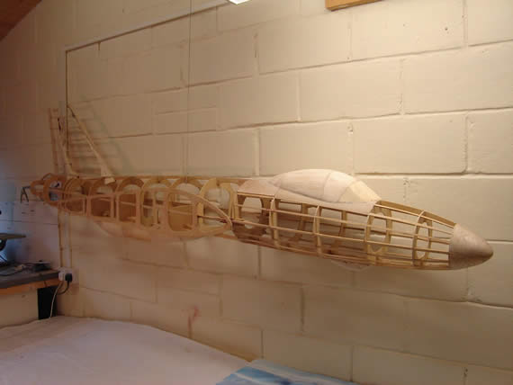
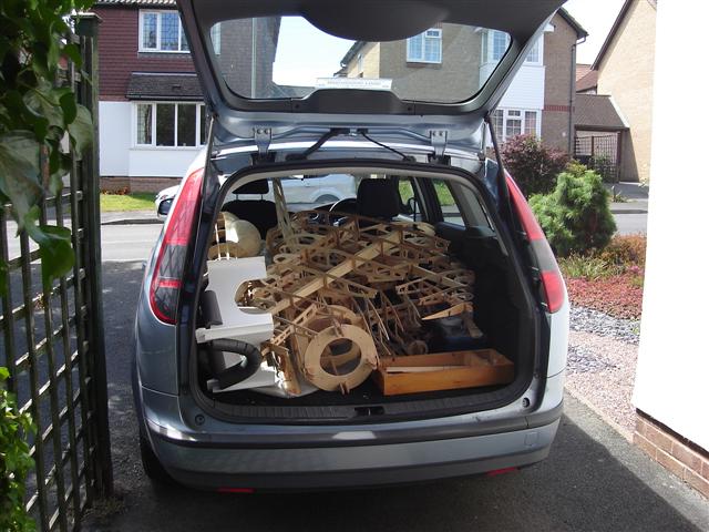
With this the size of the Vulcan is now becoming apparent. To allow for transporting, the body is built in two sections. These are held together by 4 tongue and grove joints and pinned with wing bolts.
When finished the wings will detach from the body just out board of the engines, allowing it to fit into the back of an estate car.
To date this has taken three years.
Still to do are the following:
1) Assemble the wings using the ready made ribs, spars and trailing edge.
2) Construct the elevators and ailerons, with counter balance weight.
3) Buy and install servos, battery etc.
4) Cover the structure with card, tissue and dope (or glass cloth?).
5) Paint and add decals
6) Add balance weights and programme the radio.The final statistics should be;
Span 10 feet
Length 9 feet
Height 29 inches
Weight 25-27 lbsGiven the size and weight it will be difficult to hand launch.Which is why the blue steel missile has been built into the underside of the wing. I propose to launch using a short bungy. The model will sit on a trolley pulled by the bungy .
How long will this all take? Well, probably longer than the time being spent refurbishing the original!
Further details to follow.Regards. Dave
New Pictures From Dave